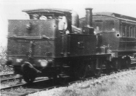
| The A(N&SW)D&R purchased 14 from the GWR in 1911. It had been part of the 517 class and was built in 1877. Why the GWR sold such a popular and useful engine is a mystery. It was used by the A(N&SW)D&R to haul one or two coaches on the Machen to Pontypridd service. |
|---|
|
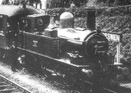
Amazingly two photos have come to light of it in its early ADR days. It looks unchanged from GWR days, except for the number on the bufferbeam. |
|---|---|
| In 1919 it received a rebuilt boiler, new safety valves and an extension to its bunker. | 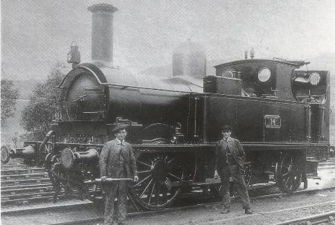
|

| Being an ex GWR engine makes modelling it easy. I have been able to use the Alan Gibson kit with only a few modifications. The chassis is a
little unusual in that it has split axles and continuous springy beam suspension. The split axles mean that each side of the chassis is
directly connected to the rails via the wheels. The frame spacers have been replaced with spacers made from PCB and the copper cut to
separate the sides electrically. The wheels of the middle and rear axles are electrically connected to the axles using conducting silver
paint. The axles themselves are split in two and joined with a plastic centre section. I found it impossible to make a split axle for the
front axle which is driven, so I used a plastic tube for the axle and Gibson sprung plunger pick ups (not shown in this early photo of the
chassis).
The continuous springy beams mean that they is only one spring down each side for all three axles. The Gibson hornguides were fitted in the normal way and then the tops were cut off. The hornblocks were fitted with small handrail knobs and little brackets fitted inside the frames. A 10 thou steel wire threads through the holes in the brackets and handrail knobs and forms a spring. If the ride is too high, then a thicker wire can be used, and weight can be added to the body to make it ride horizontal. Notice the handrail knob for the rear axle has an extension piece, as the axle is lower than the driven axles. |
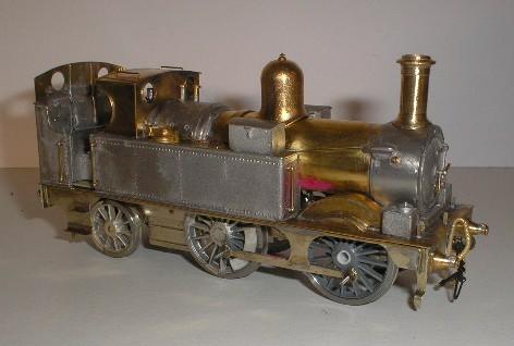
| The main departures from the kit for the body involved replacing the boiler and bunker tops with brass tube and sheet, as I was not happy with the casting provided. The bunker was 1mm wider than the footplate and this required cutting the front and back of the bunker into three parts and rejoining to make it 1/2mm narrower than the footplate. The bunker extension was cut from brass sheet using the GWR bunker extension as a partial template. Safety valves were turned from brass screws in my minidrill. | 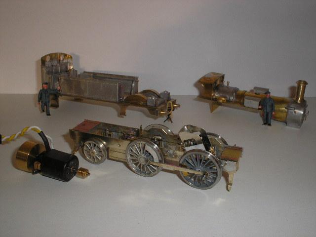 |
 |
The motor is a Mashima 1220 with the largest flywheel I could fit in (5/8" from Mainly trains). I have replaced the Gibson gearbox with a Highlevel 54:1 gearbox mainly to ensure the motor is out of the way above the springy beams. The Rear of the motor is supported using a bracket from the middle chassis spacer (which is just visable in the photo above). |
| The crank pins will be shorterned after I have painted the chassis. Also the handrails will be fitted after painting. | 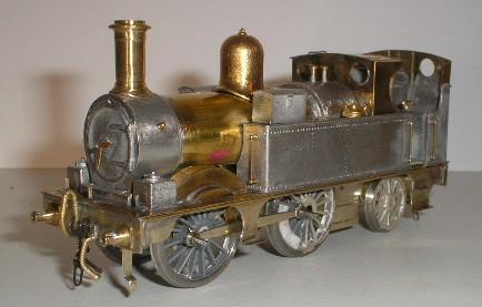 |
|
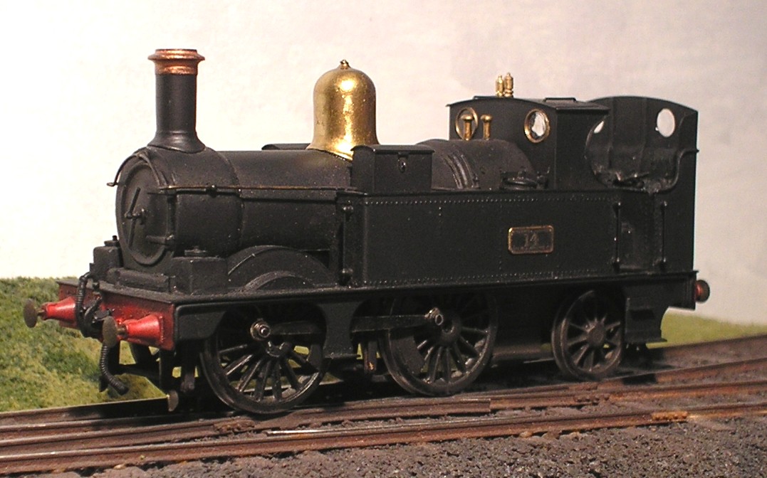
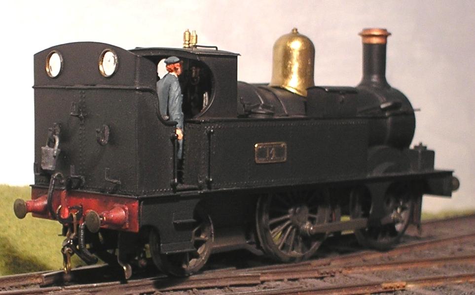
The completed model with etched number plates that I had to etch myself. |